Most cars, as they get old, tend to die a death from overheating.
A lot of the overheating happens because the rubber hoses get brittle and fissure and at pressure they tend to break and let go all the coolant.
Depending on how that happens, which one it happens to and how zealous you are to the temperature gauges, you can be lucky and catch it in time, be distracted and catch it too late, or just be unlucky and have one of the lower end hoses go and not have a chance to catch the issue before the engine overheats.
Some cars are equipped with a coolant low indicator... but others aren't.
I was very surprised and UPSET at Volvo, when I found out that my 1997 v70 t5 HAD a coolant lever indicator, but the 2006 V50 T5 AWD from my wife didn't!
My guess? somewhere along the line, (as Ford purchased Volvo) an economist on the management team, bossing the engineers decided to take 20cents profit for sensors and not install it, unlike the engineers had designed and used for decades... the usual in today's business world. He probably also thought that, as the engines started dying on their customers, they would just buy more cars... instead of changing to a better engineered brand!!! This is what happens n'our days. Economists in power.... bad decisions all the way.
However I'm and engineer and I would never accept this sort of quality reduction... so:
I went on ebay and Amazon, and brought the following list of recommended parts:
https://www.amazon.es/ELEGOO-Microcontrolador-ATmega2560-ATmega16U2-Compatible/dp/B06Y3ZHPWC/ref=sr_1_7?__mk_es_ES=%C3%85M%C3%85%C5%BD%C3%95%C3%91&dchild=1&keywords=elegoo+mega2650&qid=1626133196&sr=8-7
https://www.amazon.es/POPESQ%C2%AE-Raspberry-Generador-Frecuencia-Frequency/dp/B06XVQYF3N/ref=sr_1_5?__mk_es_ES=%C3%85M%C3%85%C5%BD%C3%95%C3%91&dchild=1&keywords=arduino+passive+buzzer&qid=1626133228&sr=8-5
https://www.amazon.es/Vosarea-Charger-Adapter-Charging-Voltmeter/dp/B07YYYP2SH/ref=sr_1_8?__mk_es_ES=%C3%85M%C3%85%C5%BD%C3%95%C3%91&dchild=1&keywords=usb+to+12v+car&qid=1626133271&sr=8-8
https://www.amazon.es/AZDelivery-128-160-p%C3%ADxeles-91-OLED/dp/B078J78R45/ref=sr_1_2?__mk_es_ES=%C3%85M%C3%85%C5%BD%C3%95%C3%91&dchild=1&keywords=oled+128%2662+i2&qid=1626133375&sr=8-2
https://www.ebay.co.uk/itm/383588215448
Did I need the MEGA instead of a simple UNO? NO! but since the car is t be driven by my wife and the Display should be more informative I added the Oled Display.. that oled display (plus variables and libraries) consume A LOT of ram and the UNO doesn't really cut it. However if you are to simplify things with a simple warning and buzzer, the uno is more than enough.
So being a Polestar V50 T5 AWD and having an oled to fool around with, I've added a couple of boot logo and boot info before the real stuff. The code is here for my example and should be adapted to your own usage.
Describing the circuit:
The liquid level readers are glued with something tough (I recommend T-REX) on the top level and bottom level of the expansion tank.
I recommend you to run a 4 wire cable all the way from the arduino place within the car to the engine bay... one for ground one for 5V and 2 for 5V return (one per sensor).
I also recommend you to create a simple oled placeholder with a 3dprinter, or use a dremmel to grind the oled location within the dashboard, assuming there is space for that.
I recommend you to place the oled in front of the existing dash on a non obstructing part of the dash, and the buzzer behind it, so it send the audio buzzing to the dashboard and this amplifies and reflects back to the driver.
Evidently the red warning led should be placed in front of the oled.
Then It is rather easy. On my code I've setup variables according to pins, you can change those and have your own project divert.
Arduino Digital IO 4 - wire to positive terminal on the buzzer
Arduino Digital IO 5 - wire to positive LED terminal arduino relay
Arduino Digital IO 6 - wire from Lower fluid level sensor RETURN line
Arduino Digital IO 7 - wire from Higher fluid level sensor RETURN line
Arduino Communication IO 20SDA - Oled SDA
Arduino Communication IO 21SCL - Oled SCL
External 5V supply:
- Liquid Sensor 1 Voltage and ground
- Liquid Sensor 2 Voltage and ground
***you can power the sensors directly on the 12v car supply, but then you need a voltage divider on the sensor return line to the arduino. I find it just easier to run a 5V supply on the sensors and reduce circuit complexity and add stability, as cars can output anywhere from 11V to 14v, depending on rpm.
Arduino 5V :
- Oled VCC
Arduino GND:
- Buzzer Ground
- Led relay Ground
12v-usb car adapter, to Ignition 12V and car ground... and then a usb cable on to your arduino.
Led :
- ground to car ground and 12V to arduino replay module, then from replay module to ignition p1 power (a.k.a. - radio power).
Logic is as follows:
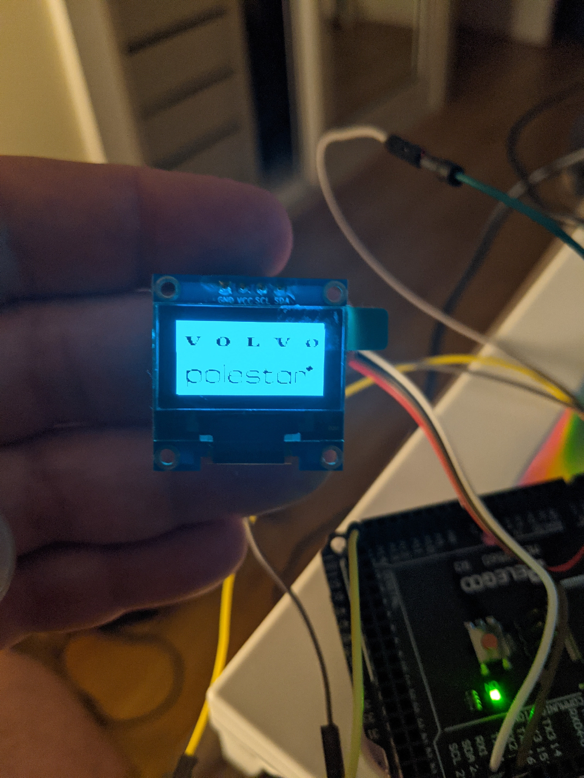
- show volvo + polestar logo on boot
- show car setup (power and AWD)
- enter loop mode with coolant level display
-If all coolant levels are good the return value is 2 and display that everything is OK
-If only the lower level is returning signal, then a refill message is displayed
-if both sensors are not returning, than coolant is bellow threshold and a Stop the car" message appears together with an annoying buzzer.
- if top sensor is returning value but the bottom is not, something is off and a "check system" message is issued with a less annoying buzzer.
The code and STL file can be found here:
https://github.com/mr1b31r0/ArduinoCarCoolantLevelWarning/tree/main
Some pictures of the project with some oled display info:


The enclosure (stl and cad files in github, together with the code).


First Assembly - buzzer + display + enclosure:


And a some poliurethane glue to bind things:

Next is the relay for the 12v bright led light:

The connectors on the Arduino board:


And a small test drive:

Installing:


Setting up the Relay module and led light (12V):


Sitting the Arduino in the car and pasing cables behind the climate control units:


The sensors and some tests:


The final install:
